Precision in sheet metal fabrication is not solely the result of advanced machinery; it begins at the drafting table. For engineers and designers, understanding the mechanical behavior of metal during the CNC bending process is essential to creating parts that are both functional and cost-effective. At FIESCO, we specialize in bridging the gap between complex CAD models and physical reality through rigorous Design for Manufacturing (DFM) principles. This guide outlines the critical variables that must be considered to optimize your designs for CNC press brake operations.
Understanding Bend Radius and Material Integrity
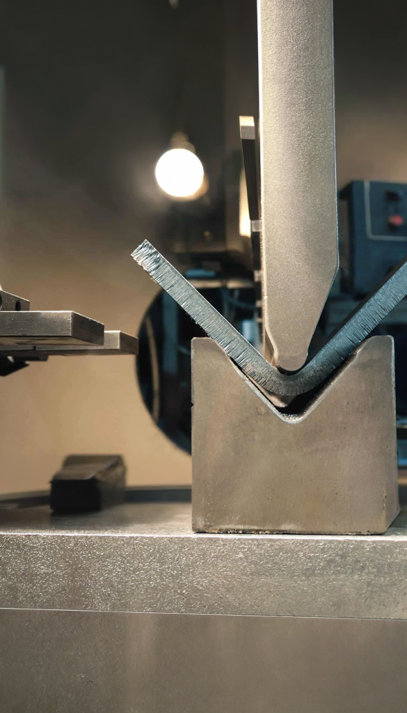
One of the most common mistakes in sheet metal design is specifying a bend radius that is incompatible with the material thickness. Every material has a minimum bend radius; attempting to bend a part tighter than this limit causes the outer grain of the metal to fracture and the inner grain to crush. This weakens the structural integrity of the component and leads to premature failure under mechanical stress.
For most industrial applications, a good rule of thumb is to maintain an inside bend radius that is at least equal to the material thickness (R=T). When designing for CNC bending, it is also vital to keep the bend radius consistent across all folds in a single part. This allows the fabricator to use a single tool setup, significantly reducing production time and minimizing the risk of setup errors.
Hole and Slot Placement Near Bends
The proximity of holes, slots, and other cutouts to a bend line is a critical factor in maintaining dimensional accuracy. When metal is folded, the material near the bend line undergoes significant stretching and deformation. If a hole is placed too close to this “deformation zone,” it will become elongated or flared, which can prevent fasteners from fitting correctly or compromise the part’s aesthetic.
To avoid distortion, holes should be placed at a distance of at least three times the material thickness (3T) from the bend line. If your design requires a hole closer to the bend, a circular or rectangular relief notch can be cut into the bend line. This “breaks” the tension in the metal and allows the hole to maintain its shape while the surrounding material is formed.
The Importance of Bend Reliefs
When a bend is made in the middle of a piece of sheet metal—rather than across the entire width—the material will tear at the edges of the bend if a relief is not provided. A bend relief is a small notch or cutout placed at the intersection of a bend and an edge. It provides a clean transition point for the metal to fold without pulling on the adjacent flat material.
Properly designed reliefs ensure that the part has a professional, clean appearance and prevent the propagation of cracks during the forming process. A standard relief should be at least as wide as the material thickness and extend slightly beyond the point where the bend begins. Incorporating these into your CAD models ensures that the CNC software interprets the geometry correctly and produces a part that matches your intent.
Managing Springback and Flange Length
Metal is inherently elastic. When the press brake releases the part, the material naturally attempts to return to its original flat shape, a phenomenon known as springback. While CNC machines use sophisticated algorithms to over-bend the part and compensate for this, designers can help by ensuring that flanges are long enough to be gripped securely by the tooling.
A flange that is too short cannot be safely or accurately formed because it will slip off the die during the stroke. As a general guideline, the minimum flange length should be at least four times the material thickness plus the bend radius (4T+R). Designing with adequate flange lengths ensures that the CNC equipment can maintain a consistent grip, resulting in highly repeatable bend angles across high-volume production runs.
Consistency and Geometric Simplification
Efficiency in CNC manufacturing is driven by consistency. Designs that utilize uniform bend angles (such as 90 degrees) and standardized material gauges allow for faster programming and reduced tool changes. While CNC technology is capable of complex, multi-stage forming, simplifying the geometry where possible reduces the likelihood of interference between the part and the machine during the bending sequence.
By adhering to these DFM principles, engineers can ensure that their designs are optimized for the high-precision environment at FIESCO. This collaborative approach between design and fabrication results in components that are stronger, more accurate, and delivered with the speed required by the modern U.S. industrial market.
For further technical insights or to start your next project, please visit our Home page.